|
|
|
Disclaimer: This document
is intended to help you, the Best Robot Builder, fix problems with the
radio control (R/C) portion of your robot. This only
troubleshoots the ‘standard’ R/C elements of your robot. The game
specific mechanisms are your responsibility.
If you haven't already done so, please read: the Generic Kit
Notes, the R/C Transmitter Manual, the speed controller manual, and the
battery charger instructions.
General Advice:
 |
Manage you batteries carefully.
Batteries like to work, so they are much happier (meaning, they will
provide more energy for your machine) when you use them up before
recharging. If you're not using them for a while, then you should
discharge them. |
|
Be careful handling small metal parts
(screws, nuts, etc.) around the Robot Box. Any parts dropped on
the Robot Box tend to find their way inside and can cause a short
circuit. |
|
Solder wire to the microswitches and to
the motor terminals (these are among the allowed solder joints).
Wires that are just wrapped around the terminals do not make good
electrical contact and will often fall off and/or create a short
circuit. |
|
Use electrical tape to insulate all
exposed electrical connections. This will help prevent short
circuits. |
|
Before applying power to the machine,
take another look at all of your connections to make sure that there
are no stray bits of wire or other misplaced metal that can cause a
short circuit. |
|
Check that you have fully inserted the
servo connectors into the robot box and that the connectors have the
proper orientation. |
|
Check that the ribbon connector between
the robot box and receiver/tether box is fully inserted in the socket.
|
|
Add some strain relief to your
wiring. Use the cable ties provided in the kit, or other methods
to protect the wires from being pulled from the terminals, or from
bending the terminals and eventually causing a short. |
|
Mount the return kit components on the
machine. You will save yourself some wiring problems and odd
behavior by properly mounting the speed controllers, servos, batteries,
etc to your machine. While Velcro is a quick and easy way to
mount parts, if you adhere the Velcro to the return parts, you are
breaking the rules. The robot box, receiver box and the speed
controllers should already have BEST applied Velcro on them, you may
not add to this Velcro, or change the position of the Velcro on these
boxes. |
Most problems fall into three categories:
- Normal
operation. It's not doing what you think it should be doing, but
it really is correct.
- Setup/Connection problem. You've made a mistake
connecting the R/C components. These normally don't damage the
components, but may blow a fuse. Double check your wiring against
the Generic Kit Notes. Check your solder joints, they should be
smooth and shiny, not grainy looking. Check the crimps on your
bullet connectors. You shouldn't be able to pull the wires out
once they have been crimped.
- Bad component. Something actually is broken and in
need of replacement from your local kit person.
To solve problems with
the R/C setup, you must understand how the system is supposed to
work. Once you understand the system (you get this knowledge by
studying the manuals for each of the components and by working with
them), it is usually not that difficult to isolate the problem to
determine which particular component is not working properly.
Frequently Appearing Symptoms:
- Everything
is dead.
- One
channel doesn't work (at all)
- A
motor attached to the ESC runs continuously
- One
motor runs slower than the other (both motors use ESCs)
- The
motor on an ESC hesitates or stalls when going from forward to
reverse (or starting out in reverse)
- A
motor runs backwards (from what you want or expect)
- A
servo moves the wrong way.

1. Problem: Everything is dead.
Check:
- Are the transmitter
and On/Off (robot) switches turned on? Normally, the servos and
Electronic Speed Controllers (ESCs) with activate briefly when the
robot is turned on. There should also be some change when the
transmitter is turned on.
- Check the meter on the transmitter. It should be move
right to the red area to indicate a fully charged battery. Note:
there may be some variation in proper meter indications between
different models of transmitters. When using the Tether Box, the
transmitter doesn't need to be turned on as long as you have the single
wire connected from the robot box to the appropriate mating connector
on the switch-fuse assembly.
- Is the battery plugged in? Are you using a charged
battery?
- Is the power lead from the robot box connected to the
pigtail on the switch assembly? This provides power for the
receiver.
- Are you using at least one ESC? Is the small switch
on one of the ESC's turned on? The ESCs contains a Battery
Elimination Circuit (BEC) that provides power to the receiver. If
the receiver doesn't have power, your machine will not
function. The small switch on the ESC turns on the BEC.
- Is the fuse blown? This is a 20 amp fuse and takes a
lot to blow it. If it has blown, check your wiring.
Disconnect the ESC and other components from the ‘Y’ connectors.
Two common problem areas that result in blown fuses are at the motor
terminals and the microswitch connections. These
positive/negative connections at these locations are very close to each
other. You need to solder the wires on the outside flats of the
contacts, not the insides. You should not need to wrap the wires
around the terminals to get a good mechanical connection. A good
solder joint will support the wire. Do not stretch the wire to
get them to length.
2. Problem: One channel doesn't work (at
all)
Check:
- Have you actually
connected to the correct channel connector? On some robot boxes,
it's easy to be off by one connector. The Channel 1 connector is
at the edge of the opening and sometimes hard to see. The three
top connectors (see the Generic Kit Notes, Figure 2) should not be
connected to anything.
- Make sure all three pins are on, not offset up or down by
one.
- Do you have the connectors oriented correctly? With
the ribbon connector to the left, the left most wire should be white if
you're connecting a servo, or yellow if you're connecting a speed
controller.
- Does the servo or speed controller (that you had on this
channel) work on another channel? If so, then try another servo/ESC on
this channel to verify that the problem is with the particular channel
and not an intermittent problem with the servo/ESC
- Check the pins on the robot box. The ribbon connector
on the side of the box should have 2 rows of pins with none bent.
The 3 pins for each channel should also be free from bends. (Bent
pins usually result from forcing the connectors on or off at an angle.)
- Check the ribbon cable connection from the Receiver or
Tether Box. You may not have a good connection unless both of the
locking ears are over the ribbon cable connector. The channel 1
signal is on one end of this connector and would be the most affected
if the connector is not plugged in correctly. The majority of
machine problems found on Game Day are the result of not having
properly connected the ribbon connector to the Robot Box.
- Try using the Tether Box in place of the Receiver Box (or
vice versa). The Robot Box is just a wiring adapter with no
active electronics. The Tether Box has a couple of components
that are particularly failure-prone. When one of these components
fail, the machine may behave oddly or not at all, when on tether.
3. Problem: A motor attached
to the ESC runs continuously
Check:
- Make sure that your
robot battery and transmitter batteries have good power. The ESC
may behave erratically if the power is too low.
- Make sure that one of ESC switches is on. Without the
ESC switch on, the receiver has no power, so you have no control signal
to the ESC, so it may do all sorts of strange things
- If the ESC behaves the same way regardless of which channel
it's connect to, then you probably need to adjust the ESC's neutral
setting.
The ESCs have a NEUTRAL
Setting. Here's how to adjust it:
- Place your robot up
on a box so that it doesn't run off the table.
- Turn the transmitter and robot on.
- Center the joystick and trim controls (on the transmitter)
for this channel. If the motor stops running at this point you
probably don't need to complete the remaining steps.
- Locate the small plastic adjustment tool from the
return kit. Only use the plastic tool for the following
operation; metallic screwdrivers can create a short circuit in the ESC
and destroy it.
- There are two adjustment holes. Locate the adjustment
slot in the NEUTRAL hole. The adjustment may not be centered in
the hole and is difficult to see. Use a flashlight, if needed,
but do not pry up the metal cover plate.
- Using the adjustment tool, rotate the adjustment until the
motor stops running. Remember this position
- Continue adjusting, in the same direction, until the motor
just starts running again.
- Finally, rotate the adjustment halfway between this
position and the position where the motor initially stopped rotating.
This sets the adjustment in the center of the dead zone.
- This motor should now respond correctly to the joystick.
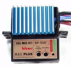 |
This
is the Electronic Speed Controller (ESC). Note the large
FULL POWER and NEUTRAL adjustments holes. The smaller hole
reveals a LED. The LED lights up red when driving in forward and
green when at full power. |
4. Problem: The
motor attached to an ESC doesn't work or is erratic
Check:
Does the problem lie in a
particular channel, or in the ESC?
- Does a servo work
when it is connected to the ESC channel? If it does, then the
channel is OK and the problem is either in the ESC or in the
motor. If not, then the channel is bad. You should be able
to get the servo to work on all four channels. Remember to keep
an ESC plugged in and turned on to provide the Receiver power.
- Does the ESC behave the same when it is connected to a
different channel? If so, then you need to check further as
described below.
Does the problem lie in
the motor or in the ESC?
- Test the ESC without
a motor. The LED on ESC should show red as the joystick is moved
in one direction. As the joystick is moved further in the same
direction, the LED should change from red to green. When the LED
glows green, the ESC is putting out full power in the forward
direction. The LED does not light up when the joystick is moved
in the opposite direction (when the ESC is putting out power for the
reverse direction. If you can't get the ESC's LED to light up
both red and green, you should check the FULL POWER setting of the ESC.
- Run the motor without an ESC. To do this, get the
battery, switch/fuse assembly and the pigtail (male connector with
short wire leads). Hook up the pigtail to the motor being
tested. (Be careful not to short the leads). Next hook up
the pigtail, switch/fuse and battery. Turning the switch ON
should cause the motor to run. If not, the motor is bad.
- Run the ESC with a different motor. Hook up a motor
that you know to be good to the ESC (either the large or small
motor will do). You should be able to control this motor.
If you cannot control a known to be good motor on a channel that is
known to be good, then the ESC is bad.
5. Problem: One
motor runs slower than the other (both motors use ESCs)
Check the Speed
adjustment on the ESCs. The FULL POWER adjustment setting on the
ESC and is adjusted in a manner similar to the NEUTRAL settting. Have a
look at the ESC instruction sheet for details. Adjust this so that
you robot runs in a (more or less) straight path when if full
forward or full reverse. Also, make sure you have good solder
joints and crimps in the wiring to both motors. A bad crimp or
solder joint will add resistance to the wiring, thus wasting power.
If your motors are too mismatched, you should contact your
kit coordinator to see if he/she can provide you with a closer matched
pair of motors. Keep in mind that a motor fresh from the
manufacturer has a +/- 10 percent acceptable variation in speed.
That means that it's possible to have two perfectly good motors with a
20 percent difference in speed. You may have to "de-tune" the
speed on the fast motor, or get used to the way the machine "pulls" to
one side.
5. Problem: The motor on an ESC hesitates
or stalls when going from forward to reverse (or starting out in
reverse)
Solution:
See: SP520+
Electronic Speed Controller Datasheet
This is normal
operation. The ESC are designed to have a short (~1/2 second)
delay when going from Forward to Reverse. This protects the ESCs
and motor gear boxes from damage. This is one of the engineering
challenges in the BEST game. Very often in the ‘real’ world,
off-the-shelf products don't do exactly what you need and sometimes
they don't even do what they claim (Imagine that!). Note that the
ESCs work better in the forward direction, so it's recommended that you
set up the ESCs and motors so that your most critical driving is in the
forward direction. In fact, the SP520's are not proportional in
reverse; the run at a fixed speed that is roughly 1/4 of the forward
speed.
6. Problem: A motor runs backwards
(from what you want or expect):
Solution:
- If the motor is
connected to the ESC, simply disconnect the bullet connectors and swap
the connections. It's a good idea to mark or record your exact
connections.
- If the motor is connected to a single microswitch, you'll
have to de-solder the wires and swap the connections.
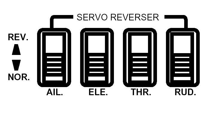
- If the motor is connected to a pair of microswitches that
reverse the motor direction, you can simply reverse the servo direction
for that channel using the reversing switches on the transmitter (see
below).
7. Problem: A servo moves the wrong way.
Solution:
Use the reversing switch
on the transmitter. This is the only to change the motion of the
servos.
|